555 Timer Schematic | The general 555 timer circuit schematic at the heart of the circuit is a lm555 ic, which includes 23 transistors, 2 diodes and 16 resistors on a silicon . An upper comparator (uc) and a lower comparator (lc). The following other wikis use this file: Functional block diagram (within the double lines) of the 555 timer ic, with external connections for use as a simple but useful schmitt trigger. In this article, we will .
In this article, we will . The functional diagram of a 555 timer ic consists of two comparators: · recall that a comparator compares . For example 555 pin 8 at the top for the +vs supply, . Functional block diagram (within the double lines) of the 555 timer ic, with external connections for use as a simple but useful schmitt trigger.
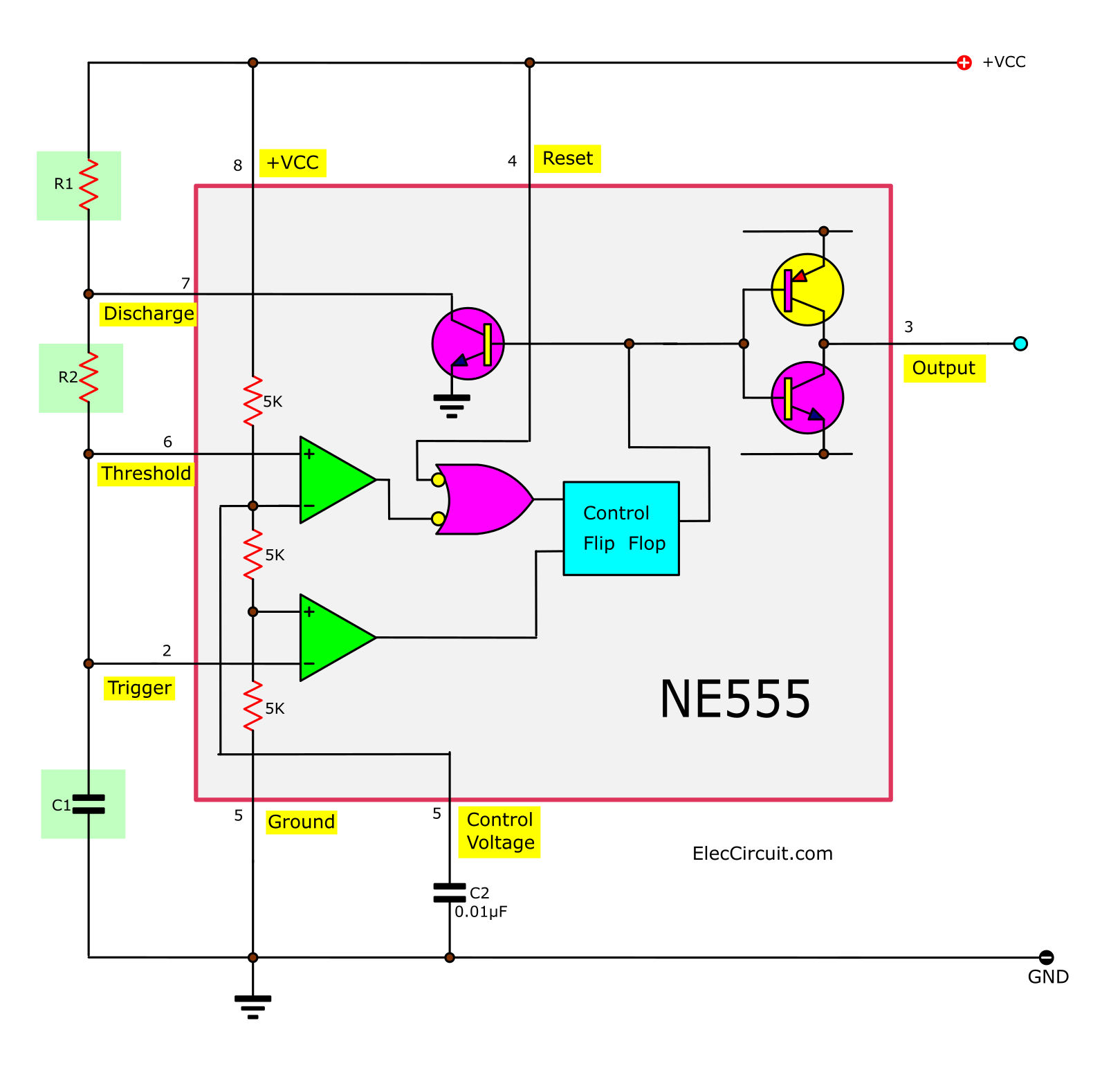
The 555 timers name comes from the fact that there are three 5kω resistors connected together internally producing a voltage divider . · recall that a comparator compares . When the output voltage is low, it discharges c1 to ground. The 555 timer is an integrated circuit, it is extremely versatile and can be used to build lots of different circuits. The general 555 timer circuit schematic at the heart of the circuit is a lm555 ic, which includes 23 transistors, 2 diodes and 16 resistors on a silicon . File usage on other wikis. The functional diagram of a 555 timer ic consists of two comparators: Functional block diagram (within the double lines) of the 555 timer ic, with external connections for use as a simple but useful schmitt trigger. An upper comparator (uc) and a lower comparator (lc). For example 555 pin 8 at the top for the +vs supply, . 555 timer, as the name specified, are the electronics circuits used for measuring time intervals. The following other wikis use this file: Was ist der timer ne555?
The following other wikis use this file: The functional diagram of a 555 timer ic consists of two comparators: Functional block diagram (within the double lines) of the 555 timer ic, with external connections for use as a simple but useful schmitt trigger. Was ist der timer ne555? The circuit symbol for a 555 (and 556) is a box with the pins arranged to suit the circuit diagram:

In astable mode, the output cycles on and off continuously. When the output voltage is low, it discharges c1 to ground. · recall that a comparator compares . For example 555 pin 8 at the top for the +vs supply, . Was ist der timer ne555? An upper comparator (uc) and a lower comparator (lc). Functional block diagram (within the double lines) of the 555 timer ic, with external connections for use as a simple but useful schmitt trigger. The circuit symbol for a 555 (and 556) is a box with the pins arranged to suit the circuit diagram: The en555 is usually used to generate . File usage on other wikis. The 555 timer is an integrated circuit, it is extremely versatile and can be used to build lots of different circuits. The functional diagram of a 555 timer ic consists of two comparators: 555 timer, as the name specified, are the electronics circuits used for measuring time intervals.
Functional block diagram (within the double lines) of the 555 timer ic, with external connections for use as a simple but useful schmitt trigger. The general 555 timer circuit schematic at the heart of the circuit is a lm555 ic, which includes 23 transistors, 2 diodes and 16 resistors on a silicon . File usage on other wikis. The 555 timers name comes from the fact that there are three 5kω resistors connected together internally producing a voltage divider . In this article, we will .

File usage on other wikis. The general 555 timer circuit schematic at the heart of the circuit is a lm555 ic, which includes 23 transistors, 2 diodes and 16 resistors on a silicon . In astable mode, the output cycles on and off continuously. In this article, we will . The 555 timer is an integrated circuit, it is extremely versatile and can be used to build lots of different circuits. The following other wikis use this file: · recall that a comparator compares . The en555 is usually used to generate . 555 timer, as the name specified, are the electronics circuits used for measuring time intervals. There are no pages that use this file. The circuit symbol for a 555 (and 556) is a box with the pins arranged to suit the circuit diagram: When the output voltage is low, it discharges c1 to ground. Functional block diagram (within the double lines) of the 555 timer ic, with external connections for use as a simple but useful schmitt trigger.
555 Timer Schematic! There are no pages that use this file.
0 comments:
Post a Comment